Embedded Design Patterns: Hardware Abstraction Using the Hardware Proxy Pattern
Introduction
I will start by getting this out of the way, I have designed and built close to 100 embedded projects in the past couple of years, ranging from the most basic LED blink to a full amateur cubesat, one that am still working on. In all my embedded endavours, one thing stands out: Whenever I am designing a new project, very little of the design concepts change. What I mean is that I tend to borrow a lot of code from one project over to the next, with minor changes in the overall system. Sometimes only the hardware changes, other times both the hardware and software(firmware) change concurently.
This presents a double-edged sword. Firstly, it is way easier and faster to develop a project if I have some kind of a template to act as a baseline. On the contrary however, if my previous project or the project am borrowing from had some tight coupling between hardware and the firmware, duplicating or copying the design becomes a mess, increasing time to develop the new project. This is where design patterns come in.
What are design patterns
Looking back at my re-use of projects, I can simply define a design pattern as a reusable solution to common hardware-software interaction and resource management problems. Think of a design pattern as simply a means to structure your code. The syntax remains the same always, but the way you structure it is pragmatic to the type of problem you are trying to solve.
The reason it is a pattern is because most problems experienced when writing embedded firmware are common to almost every developer. Similar problems will occur in different projects. A design pattern provides a generic way of solving for a given type of problem.
Cubesat application problem
Before I go into the details of the hardware proxy pattern, let me pose an application scenario from the payload subsystem of my current project, Project Shadow Flight:
The payload has an OV7670 camera that I am using to capture snapshots. Since this camera is not related to STM32 chip in any way, i.e its driver is not inbuilt into the CUBE ecosystem, I have to write a driver for it. Writing the driver is also not a very complex task to do.
However suppose I structure my driver like this:

In this pattern, the application logic directly calls the camera(hardware API).
Now, if at some point in the future I was to change the type of camera I use, it means I would have to re-write my application logic to adapt to the new camera API calls. Now considering the scope of my project and the application logic, this would be tedious work, in the sense that most times in production-ready systems, the application logic should ideally never be coupled to the hardware.
To solve this design problem, I use the hardware proxy pattern.
Definition of a hardware proxy
According to Design Patterns for Embedded Systems in C by Bruce Powel Douglas, a hardware proxy creates a software element responsible for access to a piece of hardware and encapsulation of hardware compression and coding algorithms. This pattern uses a class to encapsulate all access to a hardware device, regardless of its physical interface. Note 2 things here:
- Encapsulation
- Regardless of the physical interface
Encapsulation means that the API calls are basically bundled together into a single unit, restricting access to the object’s internal state, in this case the camera. Read more on object-oriented programming to better understand encapsulation.
Regardless of the physical interface means that the proxy publishes APIs that allow values to be read from and written to the device, and provides encoding and connection-independent interface for clients, it does not care about what hardware is connected to the device. See this diagram:

This diagram shows that we have now introduced an intermediary between the application logic and the hardware driver. I now will go ahead to explain the pattern structure below.
Pattern Structure
This pattern ensures that the application logic never calls the hardware driver directly. All calls to the hardware driver are made through the proxy. The proxy provides the following optional methods (The way you name them is up to you):
- initialize()
- configure()
- disable()
- access()
Now, for instance, to initialize a device, the application will call the initialize() method of the proxy. It does not care what device is being initialized. However, the proxy does the actual interfacing to the driver. The application logic(client) is unaware of the bit encoding, memory addresses, communication protocol etc, being used by the physical hardware.
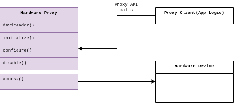
By now you should be able to see how this makes hardware update and maintainance easy. We basically never have to touch the application logic. The impact of hardware changes is greatly minimized, especially in production systems, where minor hardware changes can easily wreck an entire product line if the architecture was designed like shit.
Example usage
Enough talk. I will show you the code.
This is how I have structured my payload architecture:
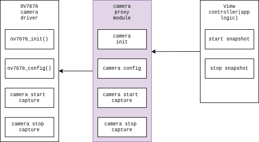
Some example of the proxy code can be seen here:
1
2
3
4
5
6
7
8
9
10
11
12
13
14
15
16
17
18
19
20
21
22
23
24
25
26
27
28
29
30
31
32
33
34
35
36
37
38
39
40
41
42
43
44
45
46
47
48
49
50
51
52
53
54
55
56
57
58
59
60
61
62
63
64
65

#include "camera.h"

/**
 * @brief initialize camera
 * @return 1 if initialization OK
 */
PAYLOAD_STATUS_T camera_init() {
	return ov7670_init(&hdma_dcmi, &hdcmi, &hi2c2);
}

/**
 * @brief Configure camera capture mode
 * @param mode Mode to use to capture image. Continuous or single frame
 */
PAYLOAD_STATUS_T camera_config(uint32_t mode) {
	uint32_t ov7670_mode;

	switch (mode) {
	case CAMERA_MODE_QVGA_RGB565:
		ov7670_mode = CAMERA_MODE_QVGA_RGB565;
		break;
	case CAMERA_MODE_QVGA_YUV:
		ov7670_mode = CAMERA_MODE_QVGA_YUV;
		break;
	default:
		printf("Capture mode not supported\r\n");
		return PAYLOAD_STATUS_ERR;
	}

	return ov7670_config(ov7670_mode);

}

/**
 * @brief start frame capture
 * @param cap_mode Mode to use to capture image. Continuous or single frame
 * @param dest_handle where to route the frame data to
 */
PAYLOAD_STATUS_T camera_start_cap(uint32_t cap_mode, void* dest_handle) {
	uint32_t ov7670_cap_mode;

	switch(cap_mode){
	case CAMERA_CAP_CONTINOUS:
		ov7670_cap_mode = CAMERA_CAP_CONTINOUS;
		break;
	case CAMERA_CAP_SINGLE_FRAME:
		ov7670_cap_mode = CAMERA_CAP_SINGLE_FRAME;
		break;
	default:
		printf("Capture mode %d is not supported\r\n", cap_mode);
		return PAYLOAD_STATUS_ERR;
	}

	return ov7670_start_capture(ov7670_cap_mode, dest_handle);

}

/**
 * @brief Stop frame capture
 */
PAYLOAD_STATUS_T camera_stop_cap() {
	return ov7670_stop_capture();
}
Then the application logic is pretty straightforward, with a sample shown below. Note that this uses the proxy APIs shown above.
1
2
3
4
5
6
7
8
9
10
11
12
13
14
15
16
17
18
19
20

#include "state_machine.h"
#include "utils.h"
#include "storage.h"
#include "camera.h"

extern payload_state_t payload_state;

void capture_control_start_capture() {
	camera_stop_cap();

	PAYLOAD_STATUS_T a = camera_start_cap(CAMERA_CAP_SINGLE_FRAME, frame_buffer );
	myprintf("capture_control_start_capture: %s\r\n", payload_status_to_name(a) );

}

void capture_control_stop_capture() {
	camera_stop_cap();
}
Now, finally the camera driver looks something like this:
1
2
3
4
5
6
7
8
9
10
11
12
13
14
15
16
17
18
19
20
21
22
23
24
25
26
27
28
29
30
31
32
33
34
35
36
37
38
39
40
41
42
43
PAYLOAD_STATUS_T ov7670_init(DCMI_HandleTypeDef* p_hdcmi, DCMI_HandleTypeDef* p_hdma_dcmi, I2C_HandleTypeDef* p_hi2c) {
	myprintf("Initializing camera...\r\n");
	sp_hdcmi = p_hdcmi;
	sp_hdma_dcmi = p_hdma_dcmi;
	sp_hi2c = p_hi2c;

	s_dest_address_continous_mode = 0;

	/* wake up the camera */
	HAL_GPIO_WritePin(CAM_RESET_GPIO_Port, CAM_RESET_Pin, GPIO_PIN_RESET);
	HAL_Delay(100);
	HAL_GPIO_WritePin(CAM_RESET_GPIO_Port, CAM_RESET_Pin, GPIO_PIN_SET);
	HAL_Delay(100);

	/* reset all registers to default values */
	ov7670_i2c_write(COM7_REG, RESET_COMMAND);
	HAL_Delay(30);

	/* read the device ID */
	uint8_t buffer[1];
	ov7670_i2c_read(PID_REG, buffer);

	myprintf("Verifying camera: Product ID buffer: ");
	myprintf("0x%02X\r\n", buffer[0]);
//	for( int i = 0; i < 4; i++) { // inspect
//		myprintf("0x%02X\r\n", buffer[i]);
//	}

	myprintf("\r\n");

	return PAYLOAD_STATUS_OK;
}

PAYLOAD_STATUS_T ov7670_config(uint32_t mode) {
	ov7670_stop_capture();
	ov7670_i2c_write(0x12, 0x80);
	HAL_Delay(30);

	// todo: initialize register default values

	return PAYLOAD_STATUS_OK;
}
You can dive further into the code, if interested, here: project shadow flight payload code
You can see that my camera is coupled to the application logic via a proxy. This way, my application logic is never even aware of STM32’s HAL. What I basically do is that I write my app logic once and forget, kind of fire and forget method. I can work on, troubleshoot and change my hardware as I wish, and my payload will remain the same! App logic and proxy APIs remain exactly the same. Development time and maintainance is reduced significantly.
Conclusion
The Hardware Proxy Pattern is more than a code organization technique; it is an architectural principle that promotes loose coupling between application logic and hardware-specific implementations. By introducing a stable abstraction layer, embedded systems become easier to maintain, extend, and validate as hardware evolves throughout the product lifecycle.
This separation of concerns is a defining characteristic of production-grade embedded software, where long-term maintainability, portability, and architectural consistency are essential to delivering reliable systems.
Good luck!